In this post i will shed some light on some spanning-tree info that has been floating around. But also an explanation why i choose a non-obvious answer to an IPexpert question.
Specifically 2 things.
The first one is the selection of ports and what _exactly_ selects the root port.
The second thing is selection of a designated bridge and why the typical phrasing of a question might also be more complex than what you expect.
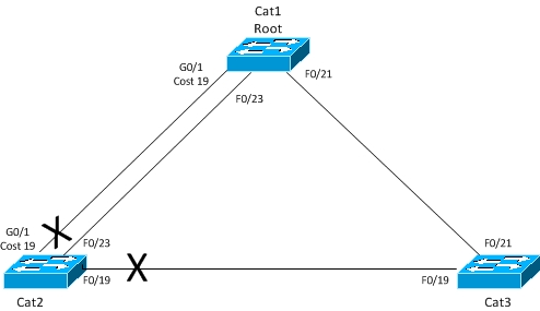
The topology i will be using is as such:
(Note: Please pay attention to the fact that i have manually modified the cost of the G0/1 interface on Cat1 and Cat2 in order to be able to use this port in the output below).
Topic 1:
——–
Lets start out with a premise that states, that a root port is selected based on the following:
-
Lowest Path Cost to Root Bridge
-
Lowest Sender Bridge ID
-
Lowest Sender Port ID
I will go through tiebreak number 1 quite fast, since the lowest cost path to the root will always be chosen.
This is the case for our Cat3 switch. The lowest cost path is through F0/21 with a path cost of 19 (Cat1 sends out cost = 0 and Cat3 adds 19). We can verify this:
Cat2 on the other hand has two links with equal cost between them (because i manually set the cost on both Cat1 and Cat2). So which one to choose?
Well, the next tiebreaker down the list states the lowest sender bridge ID. Since both links are from the same switch, this tiebreaker cant be used.
The third one down the list is where the action takes place. While “Lowest Sender Port ID” can be considered correct, i dont fully agree with it. Its more complex than a simple number. Each Port ID is combined of the Port Priority (default is 128) and the locally assigned Port Number. All of this is on the sender bridge!
Lets take a look on Cat1:
Its a long output, but with lots of useful information. What we are interested in, is port 23 and port 49. Port 23 is F0/23 and Port 49 is G0/1. Each of these has a Priority of 128 at the moment. The combined Port ID is then 128.23 for F0/23 and 128.49 for G0/1.
So right now we should see F0/23 (128.23) being the Root Port on Cat2:
And with more detail:
Everything looks fine. We now have a topology that looks like this:
But lets change the Priority on Cat1’s G0/1 interface:
And verify on Cat2:
We can see that it indeed has changed.
Our topology now looks like this:
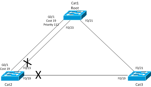
So this means that Port Priority is an important part of the Port ID, so simply saying Lowest Sender Port ID, is correct, but only half the truth.
Topic 2:
———-
The second thing is in a way related to Topic 1.
As with Topic number 1, for a given segment, a designated bridge needs to be selected. Take the link between Cat2 and Cat3. Either Cat2 or Cat3 needs to be the designated bridge and have its link being in a forwarding state. The other bridge will put its link into a blocking state.
The Tiebreaker here will be the sending bridge with the lowest Bridge ID, which is made up of the priority of the sending bridge along with its Mac address.
Seeing as the Mac address will be unique, this will be the Tie Breaker. Thats why i in my comment stated that mac address will be a tiebreaker, all other things being equal.
To verify this:
We can see that the F0/19 link is blocking, meaning that Cat3 is the designated switch, which we verify here:
F0/19 is in a forwarding state and it is designated.
If we run the following on each switch:
We clearly see that Cat3 has the lowest total Bridge ID.
I hope that by explaining these two topics, you will realize _why_ something as “Sender Port ID” and “Sender Bridge ID” cause a selection and simply not reiterate what books tell you.