Frame-Relay PVC bundle
In this short piece i would like to show how Frame-Relay PVC bundles work.
A PVC bundle is exactly what the name says. Its a bundle of PVC’s, with each PVC handling a certain Precedence, MPLS EXP or DSCP.
A requirement for the PVC bundle is that all IP Precedence or DSCP values will be handled by one of the PVC’s, so you need to set the “default” PVC unless
you map them all manually. The PVC bundle will not come up unless you do this.
If a certain individual VC fails, traffic is by default allowed to “bump” to another VC.
If individual protection is enabled, what this means if that the protected VC goes down, the entire PVC bundle goes down.
If group protection is enabled for some of the VC’s, all of the links in the group needs to go down in order for the entire PVC bundle to go down.
Only 1 group can be used for a PVC bundle.
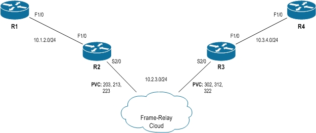
In my example below, i will be using R1 and R4 for generating and receiving traffic.
R2 and R3 is where the magic happens and the PVC bundle is defined.
The topology is as such:
For this example, i have defined 3 PVC’s on the Frame-Relay switch. For R2, these DLCI’s are 203, 213 and 223. For R3 these corresponds to 302, 312 and 322.
I am running EIGRP AS 100 on all the routers to provide connectivity.
Lets see how we define our PVC bundle on R2:
interface Serial2/0
 ip address 10.2.3.2 255.255.255.0
 encapsulation frame-relay
 serial restart-delay 0
 frame-relay vc-bundle MAIN
  pvc 203 VC-A
   precedence 7
  pvc 213 VC-B
   precedence 5
  pvc 223 VC-C
   precedence other
 frame-relay map ip 10.2.3.3 vc-bundle MAIN broadcast
end
Here we define a PVC bundle called MAIN. This is an abitrary name that will be referenced later to use the PVC bundle.
Within the bundle we define each of our DLCI’s as well as give each one of them another abitrary name.
In our example we have chosen to use precedence values. Either IP Prec, MPLS EXP or DSCP can be used, but only one of them.
This means that we must have all values between 0 to 7 mapped out in some way.
I have selected to use VC-A (DLCI 203) for precedence 7 and VC-B (DLCI 213) for precedence 5 and everything else maps to VC-C (DLCI 223).
Finally i make the L2->L3 mapping using the frame-relay map command and using the name for the PVC bundle that was defined earlier.
The same sort of configuration is happening on R3:
interface Serial2/0
 ip address 10.2.3.3 255.255.255.0
 encapsulation frame-relay
 serial restart-delay 0
 frame-relay vc-bundle MAIN
  pvc 302 VC-A
   precedence 7
  pvc 312 VC-B
   precedence 5
  pvc 322 VC-C
   precedence other
 frame-relay map ip 10.2.3.2 vc-bundle MAIN broadcast
end
We can verify our PVC bundle using the “show frame-relay vc-bundle” command:
R2#sh frame vc
MAIN on Serial2/0 - Status: UP  Match-type: PRECEDENCE
Name    DLCI  Config.         Active          Bumping     PG/ CIR   Status
              level           level           to/ accept  PV  kbps
VC-A    203   7               7               6/Yes       -   -     up
VC-B    213   5               5               4/Yes       -   -     up
*VC-C   223   0-4,6           0-4,6           -/Yes       -   -     up
Packets sent out on vc-bundle MAIN : 75
In this output we can see that we have 3 VC’s in the PVC bundle, what Precedence value they are each carrying and how the “bump” strategy will work in case the VC goes down.
The * marks the default VC.
We also see that all the VC’s are up.
Now lets try and generate some traffic on R1 to R4 and run a packet capture on traffic sent out by R2 to verify if the mappings are working correctly.
First off is traffic marked with Precedence 7. This traffic should use VC-A (DLCI 203).
First, lets work out which decimal values to use in our ping tests:
IP Prec 7:
111 00000 = 224
IP Prec 5:
101 00000 = 160
On R1, lets make an extended ping:
R1#ping
Protocol [ip]:
Target IP address: 10.3.4.4
Repeat count [5]:
Datagram size [100]:
Timeout in seconds [2]:
Extended commands [n]: y
Source address or interface:
Type of service [0]: 224
Set DF bit in IP header? [no]:
Validate reply data? [no]:
Data pattern [0xABCD]:
Loose, Strict, Record, Timestamp, Verbose[none]:
Sweep range of sizes [n]:
Type escape sequence to abort.
Sending 5, 100-byte ICMP Echos to 10.3.4.4, timeout is 2 seconds:
!!!!!
Success rate is 100 percent (5/5), round-trip min/avg/max = 72/88/124 ms
And the packet capture:
From this we can see that the DLCI being used is as expected DLCI 203 (VC-A).
Lets try out IP Precedence 5:
R1#ping
Protocol [ip]:
Target IP address: 10.3.4.4
Repeat count [5]:
Datagram size [100]:
Timeout in seconds [2]:
Extended commands [n]: y
Source address or interface:
Type of service [0]: 160
Set DF bit in IP header? [no]:
Validate reply data? [no]:
Data pattern [0xABCD]:
Loose, Strict, Record, Timestamp, Verbose[none]:
Sweep range of sizes [n]:
Type escape sequence to abort.
Sending 5, 100-byte ICMP Echos to 10.3.4.4, timeout is 2 seconds:
!!!!!
Success rate is 100 percent (5/5), round-trip min/avg/max = 68/79/88 ms
And the capture:
Excellent, DLCI 213 (VC-B), is used.
Finally, lets make a generic ping to test the final VC in the PVC bundle:
R1#ping 10.3.4.4
Type escape sequence to abort.
Sending 5, 100-byte ICMP Echos to 10.3.4.4, timeout is 2 seconds:
!!!!!
Success rate is 100 percent (5/5), round-trip min/avg/max = 44/68/124 ms
The capture for default traffic:
And finally we see the default PVC (VC-C) being used to handle everything else.
And with that i will close out.


