Practical OTV
————-
This post is all about OTV (Overlay Transport Virtualization) on the CSR1000v.
I wanted to create the post because there are alot of acronyms and terminology involved.
A secondary objective was to have a “real” multicast network in the middle, as the examples I have seen around the web, have used a direct P2P network for the DCI.
Instead, I wanted to have full multicast running in the SP core in order to gain a full understanding of the packet forwarding and encapsulation.
First off, lets talk about the topology I will be using:
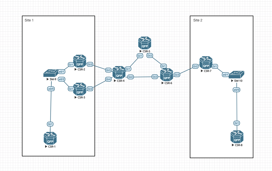
Datacenters:
————
We have 2 Datacenters, one represented by Site 1 and the other by Site 2.
In the middle, we have what is in all respects a SP provider network. In your environment, this may or may not be your own transport network.
In site 1, CSR-1 is our “server”, basically all thats configured on it is an IP address (192.168.100.1/24) on its G1 interface.
SW-9 is our L2 switch, which is configured with 2 VLAN’s (Vlan 100 (SERVER-VLAN) and Vlan 900 (SITE-VLAN)). The port (e0/0) going to CSR-1 is configured as an access-port in Vlan 100.
The ports going to CSR-2 and CSR-3 (e0/1 and e0/2) are trunk ports.
In site 1, the CSR-2 and CSR-3 routers are our OTV Edge devices, which is basically just a naming convention to designate your OTV encapsulation/decapsulation devices. In site 1 we are running two of these in order to show how the redundancy is performed.
Site 2 is very similar, although here I have selected to only have 1 OTV edge device (CSR-7).
In all sites, our OTV edge devices use their G2 interface as whats called their “Join Interface”. All that really means is that this is the L3 interface going towards the DCI “cloud”.
Also on all OTV edge devices, the G1 port is a L2 only interface, connecting to the internals of the respective site.
Transport Network:
——————
We have OSPF running as our IGP between all devices, providing full unicast reachability between our routers.
Inside the transport network, we are running Any Source Multicast (ASM), with the Rendevouz Point (RP) being the loopback0 interface of CSR-5 (5.5.5.5/32). All other routers (CSR-4 and CSR-6) having statically this RP configured.
Its important to note that no PIM adjacency exists between CSR-2 and CSR-4, and the same between CSR-3 and CSR-4. And the other way around no PIM adjacency exists between CSR-6 and CSR-7 either.
The only thing thats required is that we enable PIM on the link on CSR-4 and CSR-6. The reason behind that is that in IOS configuration, this is what also enables IGMP which is what we are really after in this solution. So you can think of CSR-2, CSR-3 and CSR-7 as “clients” of the multicast network sending IGMP joins (actually these are reports) to the transport network, which then handles the real multicast forwarding.
Terminology:
————
We have already covered quite a bit of terminology in the previous introduction, but let me iterate a few here:
– Join interface = Simply the L3 interface on the edge device, which face the transport network.
– Edge Device = Just an OTV router. Sits at the boundary between the L2 network you want transported and the L3 transport network.
– AED Device = Authoritive Edge Device. This is the “active” router, doing the transport of a certain VLAN. Only 1 AED for each VLAN on the site.
– Site VLAN = The Edge devices need to elect an AED for each VLAN that needs transporting. This is the function of the Site VLAN.
– Internal Interface = A L2 interface going towards the internal datacenter site. This is where we receive the frames we need to extend across OTV.
– Overlay Interface = The logical representation within Cisco IOS that ties all the pieces together.
Verification:
————-
Enough theory, lets see this beast in action on the command-line.
First off is our “servers”, which is CSR-1 and CSR-8:
and CSR-8:
Very simple. Nothing else of interest is configured on these devices, they simply serve as our validation platform.
What about the configuration on SW-9?
And we can see the spanning-tree result for this configuration:
Everything looks good so far!
Now for the interesting part, which is CSR-2, CSR-3 and CSR-7:
CSR-2:
First off, we set our Site Vlan to be 900, which is again what is used for AED election, locally to the site. This Vlan should never be extended over the OTV tunnel.
Then i set the identifier for our site. This is what is used in the loop prevention, so its very important that this is unique per site!
In the overlay interface configuration, I define a few things. The first of which is the multicast configuration, where we use group address 239.1.1.1 for our control traffic and 232.1.1.0/24 for data traffic. Next I specify that our Join interface is GigabitEthernet2. Finally I configure that we want to extend vlan 100 through the use of a service instance configuration snippet.
Toward the L2 site, we have GigabitEthernet1, where I have configured a L2 configuration using two Vlan’s. We want to have the router “listening” to both our Site Vlan (900) and our Data or Server Vlan (100) which is the one we want to extend across our DCI.
Last, but not least, we have GigabitEthernet2, which is our Join interface. This is a standard L3 interface configuration, with two important statements. First is “ip pim passive” which makes the interface run multicast, but not establish any pim adjacency and the other is “ip igmp version 3” which in effect makes the interface able to utilize SSM.
On CSR-3, the exact same configuration is present, with the exception of a different Join interface IP address:
Lets use some verification commands to see if everything is as we expect:
The first of which is “show otv adjacency”:
This command verifies that we have ISIS adjacencies up and running toward both CSR-3 (in site: 0001.0001.0001) and CSR-7 in site 0002.0002.0002, which is a very good start.
Next command i want, is to check if our Server vlan (100) is active on CSR-2 and CSR-3 (remember that only one of the routers should be active for this purpose):
This command states that for Vlan 100, the AED is CSR-3 and that CSR-2 (this router) is inactive for this Vlan.
The reverse should be true when looking at CSR-3:
Thankfully this output verifies this behavior!
For site 2, we only have one edge device, so this router (CSR-7) should be the AED for site 2:
Which it indeed is.
For the next verification, I need to figure out the Mac addresses of our “servers”, namely CSR-1 and CSR-8:
So lets check out whether or not we have those Mac address announced through the OTV control plane:
On CSR-3 in Site-1:
Great! – We see both addresses, one on our G1 interface on the service 100 instance, which is the L2 interface going to our local server and another address known from CSR-7 from Site-2!
The opposite should be true from CSR-7’s point of view:
To complete the picture of the solution, I would like to show the state of the transport network from a multicast perspective.
CSR-2 and CSR-3 should send an IGMP join/report to select traffic from 239.1.1.1 group which we previously configured, so lets check out if CSR-4 receives this:
Excellent, CSR-4 has received information on both the G3 and G4 interface, going to CSR-2 and CSR-3 respectively.
When we in turn uses this IGMP, our multicast network, built by PIM should have some state information created:
This rather large output confirms that we have a (*,G) entry for 239.1.1.1 going to our RP which is CSR-5 and we have individual (S,G) from each of our OTV edge devices!
Somewhat the same information should be present on CSR-6:
Which indeed is the case.
So now that we have established that all the control-plane technology is working, lets try out the data-plane from CSR-1 to CSR-8:
And thats it!
To summarize, what I have gone through in this post, is how to use the CSR1K platform to provide for DCI (Data Center Interconnect) using OTV. We have gone through the configuration of the individual devices, as well as having provided a “real” multicast transport network. We then verified the control-plane information and lastly we tested our dataplane connectivity.
I hope you have enjoyed this post!