In this post I would like to show how its possible to use a fairly new protocol, LISP, to interconnect IPv6 islands over an IPv4 backbone/core network.
LISP stands for Locator ID Seperation Protocol. As the name suggest, its actually meant to decouple location from identity. This means it can be used for such cool things as mobility, being VM’s or a mobile data connection.
However another aspect of using LISP involves its tunneling mechanism. This is what I will be using in my example to provide the IPv6 islands the ability to communicate over the IPv4-only backbone.
There is alot of terminology involved with LISP, but i will only use some of them here for clarity. If you want to know more about LISP, a good place to start is http://lisp.cisco.com.
The topology i will be using is a modified version of one presented in a Cisco Live presentation called “BRKRST-3046 – Advanced LISP – Whats in it for me?”. I encourage you to view this as well for more information.
Here is the topology:
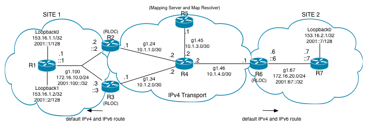
Some background information about the setup. Both Site 1 and Site 2 are using EIGRP as the IGP. Both IPv4 and IPv6 is being routed internally. A default route is created by R2, R3 and R6 in their respective sites.
The RIB on R1 for both IPv4 and IPv6:
And R7:
Now in order to get anywhere, we need to setup our LISP infrastructure. This means configuring R2, R3 and R6 as whats known as RLOC’s as well as configuring R5 as a mapping-server and map-resolver. A mapping server/resolver is where RLOC’s register what internal IP scopes they have in their sites. Its also where each RLOC asks for information on how to reach other sites. So obviously they are a very important part of our LISP setup. Here is the relevant configuration on R5:
On IOS-XE which is what im using to build this lab, all configuration is being done under the router LISP mode.
As can be seen from the configuration, two sites have been defined, SITE1 and SITE2.
An authentication key has been configured for each site. Furthermore, the prefixes that we want to accept from each site has also been configured. If our addressing scheme had been somewhat more thought out we could use the “accept-more-specifics” to accept more specific subnets, but this configuration serves our purpose.
Pay attention to the fact that we do this for each address-family. For our IPv6 example this is really not nessecary, but i wanted to provide both IPv4 and IPv6 connectivity, so i configured both.
Finally I’ve configured R5 as both a map-server and map-resolver for each address-family.
Next up is the configuration for R2:
The first part of this configuration lists a “Locator-Set”. This is where you want to list each RLOC for the site in question. For our SITE1 we have 2 RLOC’s with IPv4 addresses in the IPv4 transport cloud being 10.1.1.1 and 10.1.2.1 respectively for R2 and R3.
One of the very cool things about LISP is how you can achieve redundancy and/or load-balancing signaled by the local RLOC’s. By modifying the priority of R3 (10.1.2.1) to 20, we have effectively told the other site(s) that we want to prefer R2 as the egress tunnel router (ETR), so all traffic would be sent to R2. However if we instead leave the priority to the same and modify the weight, we can load-balance traffic. Again this is signaled by the local site and replicated to the remote site(s).
Next up is our mappings. This is where we define which prefixes we want to use in this site. Here we have the loopbacks of R1 and the network used for connectivity in SITE 1. Both for IPv4 and IPv6. Again IPv4 is not nessecary for our example.
Finally, we define a map-resolver and map-server for both ITR (Ingress Tunnel Router) and ETR (Egress Tunnel Router). This is so we can define where we want to send our mapping data as well as where to ask for other ETR’s. We also define ourselves as ITR and ETR for both address-families.
The exact same configuration has been applied on R3:
Now for some verification commands on R2:
Lots of output. But pay attention to the fact that both ITR and ETR has been enabled and ITR Map-Resolver(s) and ETR Map-Server(s) has been defined to 10.1.3.1 (R5).
We also want to verify our current map-cache which is the cache maintained by the RLOC’s for what it already “knows” about:
Basically this output tells you that we dont know about any specific networks from other sites just yet.
R6 is very similar to R2 and R3:
And verification:
Along with the mapping-cache:
If we now try a ping from R1’s loopback0 to R7’s loopback0 we see the following:
What this tells us is that we have connectivity, but beyond that it also means that for the 2 first ICMP echo’s, location data is being retrieved. Lets now check the mapping-cache on R2:
Here we see that 2001::7/128 is currently in the cache and in order to get there we need to tunnel our traffic to the RLOC at 10.1.4.1 (R6).
On the remote side we see something similar:
This is the mapping that tells R6 that it can use both RLOC’s to send traffic to (They are both in the up state).
If we try a ping from R1 again:
We get full connectivity because the cache has already been populated.
Finally lets see what the packet capture looks like on R4:
(I used an EPC (Embedded Packet Capture) on R4 to get the data).
We clearly see that UDP traffic is flowing between R2 and R6.
So this tunneling characteristic is one way we can utilize LISP, but there are many other use cases as I mentioned before.
I hope this has been useful to you.
Until next time, take care!