In this fairly short post, id like to address a topic that came up on IRC (#cciestudy @ freenode.net). Its about how you select a route thats being redistributed into an OSPF NSSA area and comes into the OSPF backbone area 0.
For my post i will be using the very simple topology below. Nothing else is necessary to illustrate what is going on.
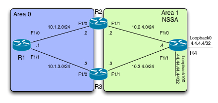
First off, id like to clarify a few things about what takes place when redistributing routes into an NSSA area.
What happens is that you have an external network, 4.4.4.4/32 in our example. This is _not_ part of the current area 1. When this network is being redistributed into area 1, its forwarding address will be set to the highest active interface of the redistributing router in the area (R4 in our case). The highest interface in the area local to the router is Loopback100 with an address of 44.44.44.44/32.
*A reader noted that a loopback address will beat a physical interface even if it has a lower address. This is true and goes for OSPF in general. Thanks!
Lets verify the configuration on R4 and the result of the redistribution to the OSPF database:
So we are running Area 1 on three interfaces connecting to R2 and R3 along with a loopback100 interface.
And the output of the relevant section of the OSPF database is:
What we are verifying here is the fact that the FA is in fact set according to the forementioned rules, namely 44.44.44.44.
Lets take a look at the OSPF configuration of R2 and R3:
And R3:
Very straigh forward so far, with the exception to the fact that i have manually set R2’s router-id, to force it to be higher than R3. This is to prove the point below.
Now what we should ideally see, is that the ABR (R2 and R3) with the highest router-id will do the type-7 to type-5 translation and preserve the FA of the type-7. What we would like to see on R1, is a type 5 LSA with a Forwarding Address of 44.44.44.44, with the advertising router be R2 (22.22.22.22). Lets check it out:
Very good, we are in fact seeing this LSA with the information we expected. We can also see something you might not expect, namely the fact that we have two paths installed in the RIB for 4.4.4.4/32. Why is that?
Well, what R1 really cares about is “how” it can get to the Forwarding Address of the route and in this case, it can get to 44.44.44.44/32 through 2 paths, R2 and R3.
Lets check out what happens if we block 44.44.44.44/32 going from Area 1 to Area 0 through R2.
Lets see what this does to the RIB of R1:
and the LSA is still the same as before:
So what this tells us, is that if the Forwarding Address is different than 0.0.0.0 (which we’ll cover in a minute) and you dont have reachability to whatever its set to, you cannot install this in the RIB.
In our case we still have one valid path through R3, so its still in the RIB, but not with load-balancing.
So to summarize what we have covered so far:
– Even though only 1 ABR creates the new type-5 (type-7 to type-5 translation), you can have load-balacing occuring.
– If you dont have a valid path to the Forwarding Address, you cannot install it in the RIB.
Lets revert our configuration on R2:
Now lets take a look at FA-Suppression!
What FA-Suppression does, is that instead of preserving the FA according to the previously mentioned rules, it sets the Forwarding Address to 0.0.0.0, indicating that the router originating the Type-5 should be used as the exit point.
We’ve already established that R2 is the router performing the Type-7 to Type-5 translation, so lets do the following configuration on R2:
What does this do to our OSPF database on R1, specifically the Type-5 LSA:
Indeed the Forwarding Address has been set to 0.0.0.0, indicating that the Advertising Router (22.22.22.22) should be used as the exit point. This also has the effect of removing our load-balancing from occuring:
So depending on how you want to “steer” your traffic, you might want to consider whether you allow the Forwarding Address through your topology and if you want to use FA suppression or not.
I hope its been useful to you!
Take care!