In this post i will show how and why to use a feature called IPv6 Prefix Delegation (PD).
IPv6 prefix delegation is a feature that provides the capability to delegate or hand out IPv6 prefixes to other routers without the need to hardcode these prefixes into the routers.
Why would you want to do this? – Well, for one is the administration overhead associated with manual configuration. If the end-customer only cares about the amount of prefixes he or she receives, then it might as well be handed out automatically from a preconfigure pool. Just like DHCP works today on end-user systems.
On top of that, by configuring a redistribution into BGP just once, you will automatically have reachability to the prefixes that has been handed out, from the rest of your SP network.
So how do you go about configuring this? – Well, lets take a look at the topology we’ll be using to demonstrate IPv6 Prefix Delegation.
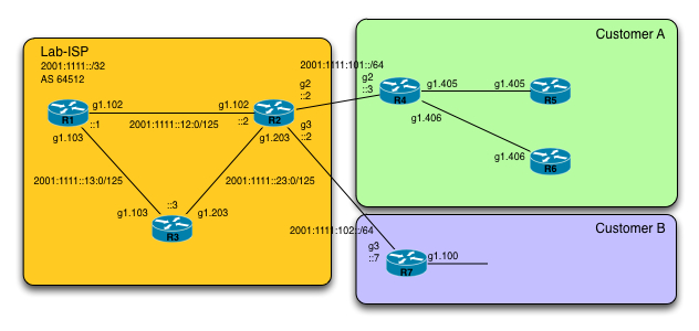
First off, we have the SP core network which consists of R1, R2 and R3. They are running in AS 64512 with R1 being a BGP route-reflector for the IPv6 unicast address-family. As an IGP we are running OSPFv3 to provide reachability within the core. No IPv4 is configured on any device.
The SP has been allocated a /32 IPv6 prefix which is 2001:1111::/32, from which it will “carve” out IPv6 prefixes to both its internal network as well as customer networks.
We are using /125 for the links between the core routers, just to make it simple when looking at the routing tables and the topology.
R2 is really where all the magic is taking place. R2 is a PE for two customers, Customer A and Customer B. Customer A is being reached through Gigabit2 and Customer B through Gigabit3. The customer’s respective CE routers are R4 and R7.
There is a link-net between R2 and R4 as well as R2 and R7. These are respectively 2001:1111:101::/64 and 2001:1111:102::/64.
So Lab-ISP has decided to use a /48 network from which to hand out prefixes to its customers. This /48 is 2001:1111:2222::/48. Lab-ISP also decided to hand out /56 addresses which will give the customers 8 bits (from 56 to 64) to use for subnetting. This is a typical deployment.
Also, since we are using a /48 as the block to “carve” out from, this gives us 8 bits (from 48 to 56) of assignable subnets, which ofcourse equals to 256 /56 prefixes we can hand out.
All of this can be a bit confusing, so lets look at it from a different perspective.
We start out with 2001:1111:2222::/48. We then want to look at how the first /56 looks like:
The 2001:1111:2222:0000::/56 is
2001:1111:2222:0000::
until
2001:1111:2222:00FF::
That last byte (remember this is all in hex) is what gives the customer 256 subnets to play around with.
The next /56 is:
2001:1111:2222:0100::/56
2001:1111:2222:0100::
until
2001:1111:2222:01FF::
We can do this all in all 256 times as mentioned earlier.
So in summary, with two customers, each receiving a /56 prefix, we would expect to see the bindings show up on R2 as:
2001:1111:2222::/56
2001:1111:2222:100::/56
So with all this theory in place, lets take a look at the configuration that makes all this work out.
First off we start out with creating a local IPv6 pool on R2:
This is in accordance to the requirements we have stated earlier.
Next up, we tie this local pool into a global IPv6 pool used specifically for Prefix Delegation:
Finally we attach the IPv6 DHCP pool to the interfaces of Customer A and Customer B:
Thats pretty much all thats required from the SP point of view in order to hand out the prefixes.
Now, lets take a look at whats required on the CE routers.
Starting off with R4’s interface to the SP:
Note that the “LOCAL-CE” is a local label we will use for the next step. It can be anything you desire.
Only when the “inside” interfaces requests an IPv6 address will a request be sent to the SP for them to hand something out. This is done on R4’s g1.405 and g1.406 interfaces:
Here we reference the previous local label “LOCAL-CE”. Most interesting is the fact that we are now subnetting the /56 prefix we have received by doing the “::1:0:0:0:1/64” and “::2:0:0:0:1/64” respectively.
What this does is that it appends the address to whats being given out. To repeat, for Customer A, this is 2001:1111:2222::/56 which will then be a final address of: 2001:1111:2222:1:0:0:0:1/64 for interface g1.405 and 2001:1111:2222:2:0:0:0:1/64 for g1.406.
Lets turn our attention to Customer B on R7.
Same thing has been configured, just using a different “label” for the assigned pool to show that its arbitrary:
And the inside interface g1.100:
Again, we are subnetting the received /56 into a /64 and applying it on the inside interface.
Going back to the SP point of view, lets verify that we are handing out some prefixes:
We can see that our local pool has handed out 2 prefixes and if we dig further down into the bindings:
We see that we do indeed have some bindings taking place. Whats of more interest though, is the fact that static routes have been created:
So two static routes that points to the CE routers. This makes it extremely simple to propagate further into the SP core:
Ofcourse some sort of filtering should be used instead of just redistributing every static route on the PE, but you get the point. So lets check it out on R3 for example:
We do indeed have the two routes installed.
So how could the customer setup their routers to learn these prefixes automatically and use them actively?
Well, one solution would be stateless autoconfiguration, which i have opted to use here along with setting the default route doing this, on R5:
and R6:
So now we have the SP core in place, we have the internal customer in place. All thats really required now is for some sort of routing to take place on the CE routers toward the SP. I have chosen the simplest solution, a static default route:
and on R7:
Finally its time to test all this stuff out in the data plane.
Lets ping from R3 to R5 and R6:
And also to R7:
Excellent. Everything works.
Lets summarize what we have done.
-
We created a local IPv6 pool on the PE router.
-
We created a DHCPv6 server utilizing this local pool as a prefix delegation.
-
We enabled the DHCPv6 server on the customer facing interfaces.
-
We enabled the DHCPv6 PD on the CE routers (R4 and R7) and used a local label as an identifier.
-
We enabled IPv6 addresses using PD on the local interfaces toward R5, R6 on Customer A and on R7 on Customer B.
-
We used stateless autoconfiguration internal to the customers to further propagate the IPv6 prefixes.
-
We created static routing on the CE routers toward the SP.
-
We redistributed statics into BGP on the PE router.
-
We verified that IPv6 prefixes were being delegated through DHCPv6.
-
And finally we verified that everything was working in the data plane.
I hope this has covered a pretty niche topic of IPv6 and it has been useful to you.
Take care!