Unified/Seamless MPLS


In this post I would like to highlight a relative new (to me) application of MPLS called Unified MPLS.

The goal of Unified MPLS is to separate your network into individual segments of IGP’s in order to keep your core network as simple as possible while still maintaining an end-to-end LSP for regular MPLS applications such as L3 VPN’s.

What we are doing is simply to put Route Reflectors into the forwarding path and changing the next-hop’s along the way, essentially stiching together the final LSP.

Along with that we are using BGP to signal a label value to maintain the LSP from one end of the network to the other without the use of LDP between IGP’s.

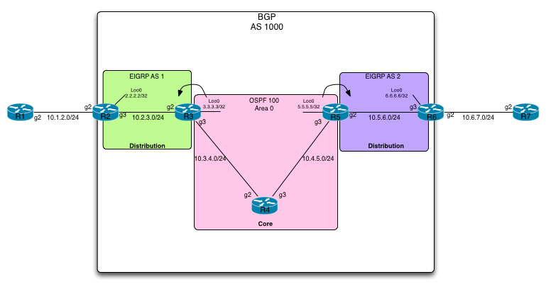
Take a look at the topology that we will be using to demonstrate this feature:

Unified-MPLS-Topology

In this topology we have a simplified layout of a service provider. We have a core network consisting of R3, R4 and R5 along with distribution networks on the right and left of the core. R2 and R3 is in the left distribution and R5 and R6 is in the right hand side one.

We have an MPLS L3VPN customer connected consisting of R1 in one site and R7 in another.

As is visisible in the topology, we are running 3 separate IGP’s to make a point about this feature. EIGRP AS 1, OSPF 100 and EIGRP AS 2. However we are only running one autonomous system as seen from BGP, so its a pure iBGP network.

Now in order to make the L3VPN to work, we need to have an end-to-end LSP going from R2 all the way to R6.

Whats is key here is that in order to have end-to-end reachability, we have contained IGP areas, each of which is running LDP for labels. However between the areas, all we are doing is leaking a couple of loopback adresses into the distribution sections from the core. These are used exclusively for the iBGP session.

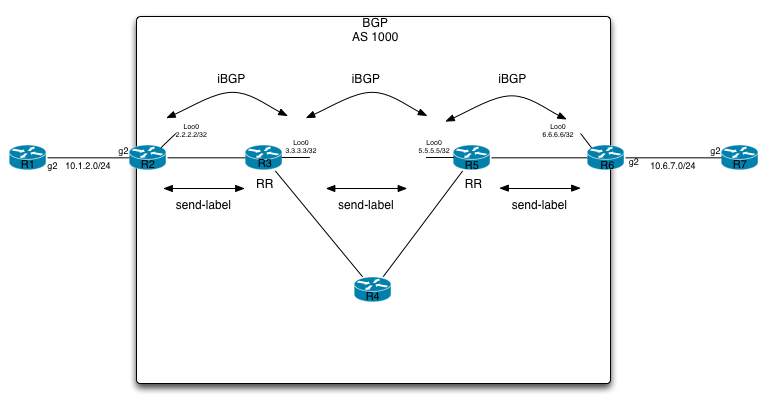
On top of that, we need to have R3 and R5 being route-reflectors, have them being in the data path as well as having them allocating labels. This is done through the “send-label” command along with modifying the next-hop (“next-hop-self all” command).

This is illustrated in the following:

Unified-MPLS-iBGP-Topology

Enough theory, lets take a look at the configuration nessecary to pull this of. Lets start out with R2’s IGP and LDP configuration:

R2#sh run | sec router eigrp
router eigrp 1
 network 2.0.0.0
 network 10.0.0.0
 passive-interface default
 no passive-interface GigabitEthernet3
R2#sh run int g3
interface GigabitEthernet3
 ip address 10.2.3.2 255.255.255.0
 negotiation auto
 mpls ip
end

Pretty vanilla configuration of IGP + LDP.

The same for R3:

R3#sh run | sec router eigrp 1
router eigrp 1
 network 10.0.0.0
 redistribute ospf 100 metric 1 1 1 1 1 route-map REDIST-LOOPBACK-MAP
 passive-interface default
 no passive-interface GigabitEthernet2
R3#sh run int g2
interface GigabitEthernet2
 ip address 10.2.3.3 255.255.255.0
 negotiation auto
 mpls ip
end
R3#sh route-map REDIST-LOOPBACK-MAP
route-map REDIST-LOOPBACK-MAP, permit, sequence 10
  Match clauses:
    ip address prefix-lists: REDIST-LOOPBACK-PREFIX-LIST
  Set clauses:
  Policy routing matches: 0 packets, 0 bytes
R3#sh ip prefix-list
ip prefix-list REDIST-LOOPBACK-PREFIX-LIST: 1 entries
   seq 5 permit 3.3.3.3/32

Apart from the redistribution part, its simply establishing an EIGRP adjacency with R2. On top of that we are redistributing R3’s loopback0 interface, which is in the Core area, into EIGRP. Again, this step is nessecary for the iBGP session establishment.

An almost identical setup is present in the other distribution site, consisting of R5 and R6. Again we redistribute R5’s loopback0 address into the IGP (EIGRP AS 2), so we can have iBGP connectivity, which is our next step.

So lets take a look at the BGP configuration on R2 all the way to R6. Im leaving out the VPNv4 configuration for now, in order to make it more visible what we are trying to accomplish first:

R2:
---
router bgp 1000
 bgp router-id 2.2.2.2
 bgp log-neighbor-changes
 neighbor 3.3.3.3 remote-as 1000
 neighbor 3.3.3.3 update-source Loopback0
 !
 address-family ipv4
  network 2.2.2.2 mask 255.255.255.255
  neighbor 3.3.3.3 activate
  neighbor 3.3.3.3 send-label
R3:
---
router bgp 1000
 bgp router-id 3.3.3.3
 bgp log-neighbor-changes
 neighbor 2.2.2.2 remote-as 1000
 neighbor 2.2.2.2 update-source Loopback0
 neighbor 2.2.2.2 route-reflector-client
 neighbor 2.2.2.2 next-hop-self all
 neighbor 2.2.2.2 send-label
 neighbor 5.5.5.5 remote-as 1000
 neighbor 5.5.5.5 update-source Loopback0
 neighbor 5.5.5.5 route-reflector-client
 neighbor 5.5.5.5 next-hop-self all
 neighbor 5.5.5.5 send-label
R5:
---
router bgp 1000
 bgp router-id 5.5.5.5
 bgp log-neighbor-changes
 neighbor 3.3.3.3 remote-as 1000
 neighbor 3.3.3.3 update-source Loopback0
 neighbor 3.3.3.3 route-reflector-client
 neighbor 3.3.3.3 next-hop-self all
 neighbor 3.3.3.3 send-label
 neighbor 6.6.6.6 remote-as 1000
 neighbor 6.6.6.6 update-source Loopback0
 neighbor 6.6.6.6 route-reflector-client
 neighbor 6.6.6.6 next-hop-self all
 neighbor 6.6.6.6 send-label
R6:
---
router bgp 1000
 bgp router-id 6.6.6.6
 bgp log-neighbor-changes
 neighbor 5.5.5.5 remote-as 1000
 neighbor 5.5.5.5 update-source Loopback0
 !
 address-family ipv4
  network 6.6.6.6 mask 255.255.255.255
  neighbor 5.5.5.5 activate
  neighbor 5.5.5.5 send-label

As visible from the configuration. We have 2 IPv4 route-reflectors (R3 and R5), both of which put themselves into the datapath by using the next-hop-self command. On top of that we are allocating labels for all prefixes via BGP as well. Lets verify this on the set:

R2#sh bgp ipv4 uni la
   Network          Next Hop      In label/Out label
   2.2.2.2/32       0.0.0.0         imp-null/nolabel
   6.6.6.6/32       3.3.3.3         nolabel/305
R3#sh bgp ipv4 uni la
   Network          Next Hop      In label/Out label
   2.2.2.2/32       2.2.2.2         300/imp-null
   6.6.6.6/32       5.5.5.5         305/500
R5#sh bgp ipv4 uni la
   Network          Next Hop      In label/Out label
   2.2.2.2/32       3.3.3.3         505/300
   6.6.6.6/32       6.6.6.6         500/imp-null
 R6#sh bgp ipv4 uni la
    Network          Next Hop      In label/Out label
    2.2.2.2/32       5.5.5.5         nolabel/505
    6.6.6.6/32       0.0.0.0         imp-null/nolabel

Since we are only injecting 2 prefixes (loopbacks of R2 and R6) into BGP, thats all we have allocated labels for.

Doing a traceroute from R2 to R6 (between loopbacks), will reveal if we truly have an LSP between them:

R2#traceroute 6.6.6.6 so loo0
Type escape sequence to abort.
Tracing the route to 6.6.6.6
VRF info: (vrf in name/id, vrf out name/id)
  1 10.2.3.3 [MPLS: Label 305 Exp 0] 26 msec 15 msec 18 msec
  2 10.3.4.4 [MPLS: Labels 401/500 Exp 0] 10 msec 24 msec 34 msec
  3 10.4.5.5 [MPLS: Label 500 Exp 0] 7 msec 23 msec 24 msec
  4 10.5.6.6 20 msec *  16 msec

This looks exactly like we wanted it to. (note that the 401 label is on a pure P router in the core).

This also means we can setup our VPNv4 configuration on R2 and R6:

R2#sh run | sec router bgp
router bgp 1000
 bgp router-id 2.2.2.2
 bgp log-neighbor-changes
 neighbor 3.3.3.3 remote-as 1000
 neighbor 3.3.3.3 update-source Loopback0
 neighbor 6.6.6.6 remote-as 1000
 neighbor 6.6.6.6 update-source Loopback0
 !
 address-family ipv4
  network 2.2.2.2 mask 255.255.255.255
  neighbor 3.3.3.3 activate
  neighbor 3.3.3.3 send-label
  no neighbor 6.6.6.6 activate
 exit-address-family
 !
 address-family vpnv4
  neighbor 6.6.6.6 activate
  neighbor 6.6.6.6 send-community extended
 exit-address-family
 !
 address-family ipv4 vrf CUSTOMER-A
  redistribute connected
  redistribute static
 exit-address-family
R2#
R6#sh run | sec router bgp
router bgp 1000
 bgp router-id 6.6.6.6
 bgp log-neighbor-changes
 neighbor 2.2.2.2 remote-as 1000
 neighbor 2.2.2.2 update-source Loopback0
 neighbor 5.5.5.5 remote-as 1000
 neighbor 5.5.5.5 update-source Loopback0
 !
 address-family ipv4
  network 6.6.6.6 mask 255.255.255.255
  no neighbor 2.2.2.2 activate
  neighbor 5.5.5.5 activate
  neighbor 5.5.5.5 send-label
 exit-address-family
 !
 address-family vpnv4
  neighbor 2.2.2.2 activate
  neighbor 2.2.2.2 send-community extended
 exit-address-family
 !
 address-family ipv4 vrf CUSTOMER-A
  redistribute connected
  redistribute static
 exit-address-family

Lets verify that the iBGP VPNv4 peering is up and running:

R2#sh bgp vpnv4 uni all sum
..
Neighbor        V           AS MsgRcvd MsgSent   TblVer  InQ OutQ Up/Down  State/PfxRcd
6.6.6.6         4         1000      16      16       11    0    0 00:09:31        2
R6#sh bgp vpnv4 uni all sum
..
Neighbor        V           AS MsgRcvd MsgSent   TblVer  InQ OutQ Up/Down  State/PfxRcd
2.2.2.2         4         1000      17      17       11    0    0 00:10:26        2

We do have the prefixes and we should also have reachability from R1 to R7 (by way of their individual static default routes):

R1#ping 7.7.7.7 so loo0
Type escape sequence to abort.
Sending 5, 100-byte ICMP Echos to 7.7.7.7, timeout is 2 seconds:
Packet sent with a source address of 1.1.1.1
!!!!!
Success rate is 100 percent (5/5), round-trip min/avg/max = 17/27/54 ms

Looks good, lets check the label path:

R1#traceroute 7.7.7.7 so loo0
Type escape sequence to abort.
Tracing the route to 7.7.7.7
VRF info: (vrf in name/id, vrf out name/id)
  1 10.1.2.2 19 msec 13 msec 12 msec
  2 10.2.3.3 [MPLS: Labels 305/600 Exp 0] 18 msec 19 msec 15 msec
  3 10.3.4.4 [MPLS: Labels 401/500/600 Exp 0] 12 msec 32 msec 34 msec
  4 10.4.5.5 [MPLS: Labels 500/600 Exp 0] 20 msec 27 msec 27 msec
  5 10.6.7.6 [MPLS: Label 600 Exp 0] 23 msec 15 msec 13 msec
  6 10.6.7.7 25 msec *  16 msec

What we are seeing here is basically the same path, but with the “VPN” label first (label 600).

So what have we really accomplished here? – Well, lets take a look at the RIB on R2 and look for the IGP (EIGRP AS 1) routes:

R2#sh ip route eigrp
..
      3.0.0.0/32 is subnetted, 1 subnets
D EX     3.3.3.3 [170/2560000512] via 10.2.3.3, 00:16:02, GigabitEthernet3
      10.0.0.0/8 is variably subnetted, 3 subnets, 2 masks
D        10.3.4.0/24 [90/3072] via 10.2.3.3, 00:16:02, GigabitEthernet3

A very small table indeed. And if we include whats being learned by BGP:

R2#sh ip route bgp
..
      6.0.0.0/32 is subnetted, 1 subnets
B        6.6.6.6 [200/0] via 3.3.3.3, 00:17:02
R2#sh ip route 6.6.6.6
Routing entry for 6.6.6.6/32
  Known via "bgp 1000", distance 200, metric 0, type internal
  Last update from 3.3.3.3 00:17:43 ago
  Routing Descriptor Blocks:
  * 3.3.3.3, from 3.3.3.3, 00:17:43 ago
      Route metric is 0, traffic share count is 1
      AS Hops 0
      MPLS label: 305

Only 1 prefix to communicate with the remote distribution site’s PE router (which we need the label for).

This means you can scale your distribution sites to very large sizes, keep your core as effecient as possible and eliminate using areas and whatnot in your IGP’s.

I hope its been useful with this quick walkthrough of unified/seamless MPLS.