In this post I would like to give a demonstration of using the Auto-Tunnel Mesh group feature.
As you may know, manual MPLS-TE tunnels are first and foremost unidirectional, meaning that if you do them between two PE nodes, you have to do a tunnel in each direction with the local PE node being the headend.
Now imagine if your network had 10 PE routers and you wanted to do a full mesh between them, this can become pretty burdensome and error-prone.
Thankfully there’s a method to avoid doing this manual configuration and instead rely on your IGP to signal its willingness to become part of a TE “Mesh”. Thats what the Auto-Tunnel Mesh Group feature is all about!
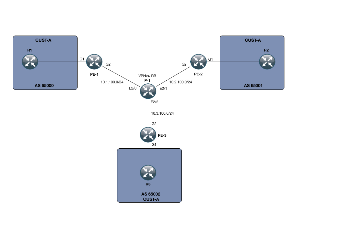
In my small SP setup, I only have 3 PE devices, namely PE-1, PE-2 and PE-3. I also only have one P node, called P-1.
However small this setup is, its enough to demonstrate the power of the Auto-Tunnel mesh functionality.
Beyond that, I have setup a small MPLS L3 VPN service for customer CUST-A, which has a presence on all 3 PE nodes. The VPNv4 address-family is using a RR which for this purpose is P-1.
We are running OSPF as the IGP of choice. This means that our Mesh membership will be signaled using Opaque LSA’s, which I will show you later on.
The goal of the lab is to use the Auto-Tunnel mesh functionality to create a full mesh of tunnels between my PE nodes and use this exclusively for label switching and to do so with a general template that would scale to many more PE devices than just the 3 in this lab.
The very first thing you want to do is to enable MPLS-TE both globally and on your interfaces. We can verify this on PE-2:
PE-2:
The second thing you want to do is to enable the mesh-feature globally using the following command as configured on PE-2 as well:
PE-2:
Starting off with MPLS-TE, we need to make sure our IGP is actually signaling this to begin with. I have configured MPLS-TE on the area 0 which is the only area in use in our topology:
PE-2:
Dont get hung up on the last configuration line. I will explain this shortly. However notice the “mpls traffic-eng area 0” and “mpls traffic-eng router-id loopback0”. After those two lines are configured, you should be able to retrieve information on the MPLS-TE topology as seen from your IGP:
PE-2:
The important thing to notice here is that we are indeed seeing the other routers in the network, all the PE devices as well as the P device.
Now to the last line of configuration under the router ospf process:
PE-2:
What this states is that we would like to use the Auto-Tunnel Mesh group feature, with this PE node being a member of group 100, using loopback0 for communication on the tunnel and running within the area 0.
This by itself only handles the signaling, but we also want to deploy a template in order to create the individual tunnel interfaces. This is done in the following manner:
PE-2:
Using the Auto-Template100 interface, we, as we would also do in manual TE, specify our loopback address, the tunnel mode and the path option. Note that here we are simply following the IGP, which sort of defeats the purpose of many MPLS-TE configurations. But with our topology there is no path diversity so it wouldnt matter anyways.
Also, the autoroute announce command is used to force traffic into the tunnels.
The important thing is the “tunnel destination mesh-group 100” which ties this configuration snippet into the OSPF one.
After everything is setup, you should see some dynamic tunnels being created on each PE node:
PE-2:
Lets verify the current RIB configuration after this step:
PE-2:
Very good. We can see that in order to reach 1.1.1.1/32 which is PE-1’s loopback, we are indeed routing through one of the dynamic tunnels.
The same goes for 3.3.3.3/32 towards PE-3’s loopback.
PE-2:
We can see that traffic towards that loopback is indeed being label-switched. And just to make it obvious, let me make sure we are not using LDP 🙂
PE-2:
On P-1, it being the midpoint of our LSP’s, we would expect 6 unidirectional tunnels in total:
P-1:
Exactly what we expected.
The following is the output of the command: “show ip ospf database opaque-area” on PE-2. I have cut it down to the relevant opaque-lsa part (we are using 2 types, one for the general MPLS-TE and one for the Mesh-Group feature):
I have highlighted the interesting parts, which is the Advertising Router and the value of the TLV, those starting with 0000 0064, which is in fact the membership of “100” being signaled across the IGP area.
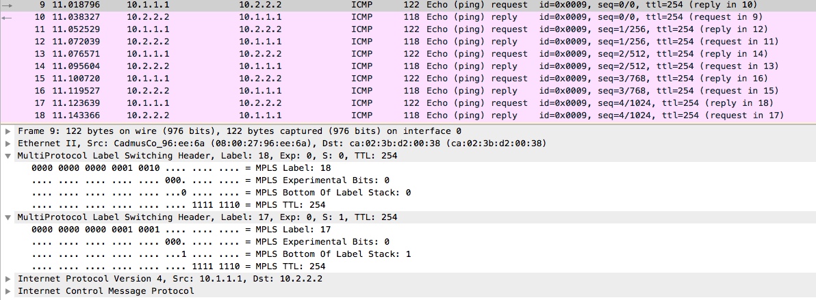
Okay, all good i hear you say, but lets do an end-to-end test from the CE devices in Customer CUST-A’s domain:
R1:
So we are learning the routes on the customer side (through standard IPv4 BGP).
R1:
We have reachability! – What about traceroute:
R1:
Just what we would expect from our L3 MPLS VPN service. A transport label (this time through MPLS-TE) and a VPN label as signaled through MP-BGP.
To round it off, I have attached the following from a packet capture on P-1’s interface toward PE-1 and then re-issued the ICMP-echo from R1’s loopback toward R2’s loopback adress:
With that, I hope its been informative for you. Thanks for reading!
References:
http://www.cisco.com/c/en/us/td/docs/ios/12_0s/feature/guide/gsmeshgr.html
Configurations: