By now, VxLAN is becoming the standard way of tunneling in the Datacenter.
Using VxLAN, i will show how to use the CSR1Kv to extend your Datacenter L2 reach between sites as well.
First off, what is VxLAN?
It stands for Virtual Extensible LAN. Basically you have a way of decoupling your vlan’s into a new scheme.
You basically map your VLAN into a VNI (Virtual Network Identifier), which in essence makes your VLAN numbering scheme locally significant.
Also, since the numbering for VNI’s is a 24 bit identifier, you have alot more flexibility than just the regular 4096 definable VLAN’s. (12 Bits .1q tags)
Each endpoint that does the encapsulation/decapsulation is called a VTEP (VxLAN Tunnel EndPoint). In our example this would be CSR3 and CSR5.
After the VxLAN header, the packet is further encapsulated into a UDP packet and forwarded across the network. This is a great solution as it doesnt impose any technical restrictions on the core of the network. Only the VTEPs needs to understand VxLAN (and probably have hardware acceleration for it as well).
Since we wont be using BGP EVPN, we will rely solely on multicasting in the network to establish who is the VTEP’s for the traffic in question. The only supported mode is BiDir mode, which is an optimization of the control plane (not the data plane), since it only has (*,G) in its multicast-routing tables.
Lets take a look at the topology i will be using for the example:
I have used a regular IOS based device in Site 1 and Site 2, to represent our L2 devices. These could be servers or end-clients for that matter. What i want to accomplish is to run EIGRP between R1 and R2 over the “fabric” using VxLAN as the tunneling mechanism.
CSR3 is the VTEP for Site 1 and CSR5 is the VTEP for Site 2.
In the “fabric” we have CSR4, along with its loopback0 (4.4.4.4/32), which is the BiDir RP and its announcing this using BSR so that CSR3 and CSR4 knows this RP information (along with the BiDir functionality). We are using OSPF as the IGP in the “fabric” to establish routing between the loopback interfaces, which will be the VTEP’s respectively for CSR3 and CSR5.
Lets verify that routing between the loopbacks are working and our RIB is correct:
on CSR3:
This means we have full reachability through the “fabric” from VTEP to VTEP.
Lets make sure our multicast routing is working properly and lets take a look at CSR4 first, since its the RP for the network:
We can see from this output that we are running PIM on all the relevant interfaces as well as making sure that bidir is enabled. We have also verified that we are indeed running BSR to announce Loopback0 as the RP.
Lets verify the multicast routing table:
We can see that we do have some (*,G) entries installed (more on the (*, 239.1.1.1) later).
Excellent.
Now lets take a sample from CSR3’s multicast configuration:
We see that we have learned the RP, its functionality as BiDir and its learned through BSR.
So far so good. Now lets turn our attention to the VxLAN part of the configuration.
The VTEP functionality is implemented by a new interface, called an NVE. This is where the configuration of which source address to use along with the multicast group to use for flooding is defined.
This is the configuration for CSR3:
Whats important here is that we will source our VTEP from loopback0 (3.3.3.3/32) and use multicast group 239.1.1.1 for the VNI 1000100. This number can be whatever you choose, i have just chosen to use a very large number and encode which VLAN this VNI is used for (Vlan 100).
On the opposite side, we have a similar configuration for the NVE:
Its very important that the multicast group matches on both sides as this is the group they will use to flood BUM (Broadcasts, Unknowns and Multicast) traffic. For example ARP.
The next configuration piece is that we need to create an EFP (Ethernet Flow Point) on the interface towards the site routers (R1 and R2) where we accept traffic tagged with vlan 100:
This configuration piece states that the encap is dot1q vlan 100 and to strip the tag inbound before further processing and add it again on egress.
Now for the piece that ties it all together, namely the bridge-domain:
Here we have a bridge domain configuration where we have 2 members. The local interface G1 on its service instance 100 and our VNI / VTEP. This is basically the glue to tie the bridge domain together end to end.
The same configuration is present on CSR5 as well.
Let verify the control plane on CSR3:
This command will show the MAC addresses learned in this particular bridge domain. On our EFP on G1 we have dynamically learned the MAC address of R1’s interface and through the NVE1 interface using VNI 1000100 we have learned the MAC address of R2. Pay attention to the fact that we know which VTEP endpoints to send the traffic to now. This means that further communication between these two end-hosts (R1 and R2) is done solely using unicast between 3.3.3.3 and 5.5.5.5 using VxLAN as the tunneling mechanism.
This command shows the status of our NVE interface. From this we can see that its in an Up/Up state. The VxLAN port is the standard destination port (4789) and we have some packets going back and forth.
Now that we have everything checked out okay in the control plane, lets see if the data plane is working by issuing an ICMP ping on R1 to R2 (they are obviously on the same subnet (192.168.100.0/24)):
This looks excellent! and in fact the EIGRP peering i had setup between them works as well:
This address is the loopback of R2.
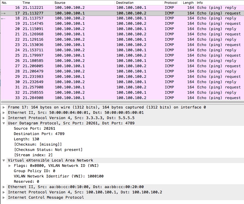
Finally i want to show how the ICMP ping works in the dataplane by doing a capture on CSR4’s G2 interface:
Here we can see a ping i issued on R1’s loopback interface towards R2’s loopback interface.
I have extended the view, so you can see the encapsulation with the VxLAN header running atop the UDP packet.
The UDP packet has the VTEP endpoints (3.3.3.3/32 and 5.5.5.5/32) as the source and destination.
The VNI is what we selected to use and is used for differentiation on the VTEP.
Finally we have our L2 packet in its entirety.
Thats all I wanted to show for now. Next time I will extend this a bit and involve BGP as the control plane.
Thanks for reading!