Practical DMVPN Example


In this post, I will put together a variety of different technologies involved in a real-life DMVPN deployment.

This includes things such as the correct tunnel configuration, routing-configuration using BGP as the protocol of choice, as well as NAT toward an upstream provider and front-door VRF’s in order to implement a default-route on both the Hub and the Spokes and last, but not least a newer feature, namely Per-Tunnel QoS using NHRP.

So I hope you will find the information relevant to your DMVPN deployments.

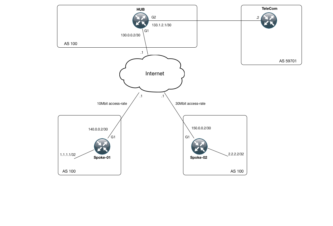
First off, lets take a look at the topology I will be using for this example:

Topology

As can be seen, we have a hub router which is connected to two different ISP’s. One to a general purpose internet provider (the internet cloud in this topology) which is being used as transport for our DMVPN setup, as well as a router in the TeleCom network (AS 59701), providing a single route for demonstration purposes (8.8.8.8/32). We have been assigned the 70.0.0.0/24 network from TeleCom to use for internet access as well.

Then we have to Spoke sites, with a single router in each site (Spoke-01 and Spoke-02 respectively).
Each one has a loopback interface which is being announced.

The first “trick” here, is to use the so-called Front Door VRF feature. What this basically allows is to have your transport interface located in a separate VRF. This allows us to have 2 default (0.0.0.0) routes. One used for the transport network and one for the “global” VRF, which is being used by the clients behind each router.

I have created a VRF on the 3 routers in our network (the Hub, Spoke-01 and Spoke-02) called “Inet_VRF”. Lets take a look at the configuration for this network along with its routing information (RIB):

HUB#sh run | beg vrf defi
vrf definition Inet_VRF
!
address-family ipv4
exit-address-family
HUB#sh ip route vrf Inet_VRF | beg Ga
Gateway of last resort is 130.0.0.1 to network 0.0.0.0
S* 0.0.0.0/0 [1/0] via 130.0.0.1
130.0.0.0/16 is variably subnetted, 2 subnets, 2 masks
C 130.0.0.0/30 is directly connected, GigabitEthernet1
L 130.0.0.2/32 is directly connected, GigabitEthernet1

Very simple indeed. We are just using the IPv4 address-family for this VRF and we have a static default route pointing toward the Internet Cloud.

The spokes are very similar:

Spoke-01:

Spoke-01#sh ip route vrf Inet_VRF | beg Gat
Gateway of last resort is 140.0.0.1 to network 0.0.0.0
S* 0.0.0.0/0 [1/0] via 140.0.0.1
140.0.0.0/16 is variably subnetted, 2 subnets, 2 masks
C 140.0.0.0/30 is directly connected, GigabitEthernet1
L 140.0.0.2/32 is directly connected, GigabitEthernet1

Spoke-02:

Spoke-02#sh ip route vrf Inet_VRF | beg Gat
Gateway of last resort is 150.0.0.1 to network 0.0.0.0
S* 0.0.0.0/0 [1/0] via 150.0.0.1
150.0.0.0/16 is variably subnetted, 2 subnets, 2 masks
C 150.0.0.0/30 is directly connected, GigabitEthernet1
L 150.0.0.2/32 is directly connected, GigabitEthernet1

With this in place, we should have full reachability to the internet interface address of each router in the Inet_VRF:

HUB#ping vrf Inet_VRF 140.0.0.2
Type escape sequence to abort.
Sending 5, 100-byte ICMP Echos to 140.0.0.2, timeout is 2 seconds:
!!!!!
Success rate is 100 percent (5/5), round-trip min/avg/max = 6/22/90 ms
HUB#ping vrf Inet_VRF 150.0.0.2
Type escape sequence to abort.
Sending 5, 100-byte ICMP Echos to 150.0.0.2, timeout is 2 seconds:
!!!!!
Success rate is 100 percent (5/5), round-trip min/avg/max = 4/16/65 ms

With this crucial piece of configuration for the transport network, we can now start building our DMVPN network, starting with the Hub configuration:

HUB#sh run int tun100
Building configuration...
Current configuration : 452 bytes
!
interface Tunnel100
ip address 172.16.0.100 255.255.255.0
no ip redirects
ip mtu 1400
ip nat inside
ip nhrp network-id 100
ip nhrp redirect
ip tcp adjust-mss 1360
load-interval 30
nhrp map group 10MB-Group service-policy output 10MB-Parent
nhrp map group 30MB-Group service-policy output 30MB-Parent
tunnel source GigabitEthernet1
tunnel mode gre multipoint
tunnel vrf Inet_VRF
tunnel protection ipsec profile DMVPN-PROFILE shared
end

There are a fair bit of configuration here. However, pay attention to the “tunnel vrf Inet_VRF” command, as this is the piece that ties into your transport address for the tunnel. So basically we use G1 for the interface, and this is located in the Inet_VRF.

Also notice that we are running crypto on top of our tunnel to protect it from prying eyes. The relevant configuration is here:

crypto keyring MY-KEYRING vrf Inet_VRF
pre-shared-key address 0.0.0.0 0.0.0.0 key SUPER-SECRET
!
!
!
!
!
crypto isakmp policy 1
encr aes 256
hash sha256
authentication pre-share
group 2
!
!
crypto ipsec transform-set TRANSFORM-SET esp-aes 256 esp-sha256-hmac
mode transport
!
crypto ipsec profile DMVPN-PROFILE
set transform-set TRANSFORM-SET

Pretty straightforward with a static pre shared key in place for all nodes.

With the crypto in place, you should have a SA for it installed:

HUB#sh crypto isakmp sa
IPv4 Crypto ISAKMP SA
dst src state conn-id status
130.0.0.2 150.0.0.2 QM_IDLE 1002 ACTIVE
130.0.0.2 140.0.0.2 QM_IDLE 1001 ACTIVE

One for each spoke is in place an in the correct state (QM_IDLE = Good).

So now, lets verify the entire DMVPN solution with a few “show” commands:

HUB#sh dmvpn
Legend: Attrb --> S - Static, D - Dynamic, I - Incomplete
N - NATed, L - Local, X - No Socket
T1 - Route Installed, T2 - Nexthop-override
C - CTS Capable
# Ent --> Number of NHRP entries with same NBMA peer
NHS Status: E --> Expecting Replies, R --> Responding, W --> Waiting
UpDn Time --> Up or Down Time for a Tunnel
==========================================================================
Interface: Tunnel100, IPv4 NHRP Details
Type:Hub, NHRP Peers:2,
# Ent Peer NBMA Addr Peer Tunnel Add State UpDn Tm Attrb
----- --------------- --------------- ----- -------- -----
1 140.0.0.2 172.16.0.1 UP 05:24:09 D
1 150.0.0.2 172.16.0.2 UP 05:24:03 D

We have 2 spokes associated with our Tunnel100. One where the public address (NBMA) is 140.0.02 and the other 150.0.0.2. Inside the tunnel, the spokes have an IPv4 address of 172.16.0.1 and .2 respectively. Also, we can see that these are being learned Dynamically (The D in the 5 column).

All is well and good so far. But we still need to run a routing protocol across the tunnel interface in order to exchange routes. BGP and EIGRP are good candidates for this and in this example I have used BGP. And since we are running Phase 3 DMVPN, we can actually get away with just receiving a default route on the spokes!. At this point remember that our previous default route pointing toward the internet was in the Inet_VRF table, so these two wont collide.

Take a look at the BGP configuration on the hub router:

HUB#sh run | beg router bgp
router bgp 100
bgp log-neighbor-changes
bgp listen range 172.16.0.0/24 peer-group MYPG
network 70.0.0.0 mask 255.255.255.0
neighbor MYPG peer-group
neighbor MYPG remote-as 100
neighbor MYPG next-hop-self
neighbor MYPG default-originate
neighbor MYPG route-map ONLY-DEFAULT-MAP out
neighbor 133.1.2.2 remote-as 59701
neighbor 133.1.2.2 route-map TO-UPSTREAM-SP out

And the referenced route-maps:

ip prefix-list ONLY-DEFAULT-PFX seq 5 permit 0.0.0.0/0
!
ip prefix-list OUR-SCOPE-PFX seq 5 permit 70.0.0.0/24
!
route-map TO-UPSTREAM-SP permit 5
match ip address prefix-list OUR-SCOPE-PFX
!
route-map TO-UPSTREAM-SP deny 10
!
route-map ONLY-DEFAULT-MAP permit 10
match ip address prefix-list ONLY-DEFAULT-PFX

We are using the BGP listen feature, which makes it dynamic to setup BGP peers. We allow everything in the 172.16.0.0/24 network to setup a BGP session and we are using the Peer-Group MYPG for controlling the settings. Notice that we are sending out only a default route to the spokes.

Also pay attention to the fact that we are sending the 70.0.0.0/24 upstream to the TeleCom ISP. Since we are going to use this network for NAT’ing purposes only, we have a static route to Null0 installed as well:

HUB#sh run | incl ip route
ip route 70.0.0.0 255.255.255.0 Null0

For the last part of our BGP configuration, lets take a look at the Spoke configuration, which is very simple and straightforward:

Spoke-01#sh run | beg router bgp
router bgp 100
bgp log-neighbor-changes
redistribute connected route-map ONLY-LOOPBACK0
neighbor 172.16.0.100 remote-as 100

And the associated route-map:

route-map ONLY-LOOPBACK0 permit 10
match interface Loopback0

So basically thats a cookie-cutter configuration thats being reused on Spoke-02 as well.

So what does the routing end up with on the Hub side of things:

HUB# sh ip bgp | beg Networ
Network Next Hop Metric LocPrf Weight Path
0.0.0.0 0.0.0.0 0 i
*>i 1.1.1.1/32 172.16.0.1 0 100 0 ?
*>i 2.2.2.2/32 172.16.0.2 0 100 0 ?
*> 8.8.8.8/32 133.1.2.2 0 0 59701 i
*> 70.0.0.0/24 0.0.0.0 0 32768 i

We have a default route, which we injected using the default-information originate command. Then we receive the loopback addresses from each of the two spokes. Finally we have the network statement, the hub inserted, sending it to the upstream TeleCom. Finally we have 8.8.8.8/32 from TeleCom 🙂

Lets look at the spokes:

Spoke-01#sh ip bgp | beg Network
Network Next Hop Metric LocPrf Weight Path
*>i 0.0.0.0 172.16.0.100 0 100 0 i
*> 1.1.1.1/32 0.0.0.0 0 32768 ?

Very straightforward and simple. A default from the hub and the loopback we ourself injected.

Right now, we are in a situation where we have the correct routing information and we are ready to let NHRP do its magic. Lets take a look what happens when Spoke-01 sends a ping to Spoke-02’s loopback address:

Spoke-01#ping 2.2.2.2 so loo0
Type escape sequence to abort.
Sending 5, 100-byte ICMP Echos to 2.2.2.2, timeout is 2 seconds:
Packet sent with a source address of 1.1.1.1
!!!!!
Success rate is 100 percent (5/5), round-trip min/avg/max = 8/17/32 ms

Everything works, and we the math is right, we should see an NHRP shortcut being created for the Spoke to Spoke tunnel:

Spoke-01#sh ip nhrp shortcut
2.2.2.2/32 via 172.16.0.2
Tunnel100 created 00:00:06, expire 01:59:53
Type: dynamic, Flags: router rib
NBMA address: 150.0.0.2
Group: 30MB-Group
172.16.0.2/32 via 172.16.0.2
Tunnel100 created 00:00:06, expire 01:59:53
Type: dynamic, Flags: router nhop rib
NBMA address: 150.0.0.2
Group: 30MB-Group

and on Spoke-02:

Spoke-02#sh ip nhrp shortcut
1.1.1.1/32 via 172.16.0.1
Tunnel100 created 00:01:29, expire 01:58:31
Type: dynamic, Flags: router rib
NBMA address: 140.0.0.2
Group: 10MB-Group
172.16.0.1/32 via 172.16.0.1
Tunnel100 created 00:01:29, expire 01:58:31
Type: dynamic, Flags: router nhop rib
NBMA address: 140.0.0.2
Group: 10MB-Group

And the RIB on both routers should reflect this as well:

Gateway of last resort is 172.16.0.100 to network 0.0.0.0
B* 0.0.0.0/0 [200/0] via 172.16.0.100, 06:09:37
1.0.0.0/32 is subnetted, 1 subnets
C 1.1.1.1 is directly connected, Loopback0
2.0.0.0/32 is subnetted, 1 subnets
H 2.2.2.2 [250/255] via 172.16.0.2, 00:02:08, Tunnel100
172.16.0.0/16 is variably subnetted, 3 subnets, 2 masks
C 172.16.0.0/24 is directly connected, Tunnel100
L 172.16.0.1/32 is directly connected, Tunnel100
H 172.16.0.2/32 is directly connected, 00:02:08, Tunnel100

The “H” routes are from NHRP

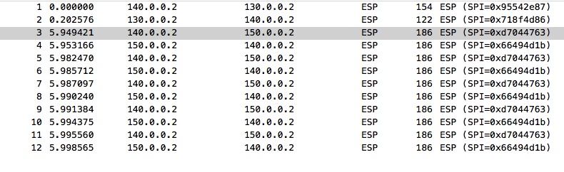
And just to verify that our crypto is working, heres a capture from wireshark on the internet “Cloud” when pinging from Spoke-01 to Spoke-02:

wireshark

Now lets turn our attention to the Quality of Service aspect of our solution.

We have 3 facts to deal with.

1) The Hub router has a line-rate Gigabit Ethernet circuit to the Internet.

2) The Spoke-01 site has a Gigabit Ethernet circuit, but its a subrate to 10Mbit access-rate.

3) The Spoke-02 site has a Gigabit Ethernet circuit, but its a subrate to 30Mbit access-rate.

We somehow want to signal to the Hub site to “respect” these access-rates. This is where the “Per-Tunnel QoS” feature comes into play.

If you remember the Hub tunnel100 configuration, which looks like this:

interface Tunnel100
ip address 172.16.0.100 255.255.255.0
no ip redirects
ip mtu 1400
ip nat inside
ip nhrp network-id 100
ip nhrp redirect
ip tcp adjust-mss 1360
load-interval 30
nhrp map group 10MB-Group service-policy output 10MB-Parent
nhrp map group 30MB-Group service-policy output 30MB-Parent
tunnel source GigabitEthernet1
tunnel mode gre multipoint
tunnel vrf Inet_VRF
tunnel protection ipsec profile DMVPN-PROFILE shared

We have these 2 “nhrp map” statements. What these in effect does is to provide a framework for the Spokes to register using one of these two maps for the Hub to use to that individual spoke.

So these are the policy-maps we reference:

HUB#sh policy-map
Policy Map 30MB-Child
Class ICMP
priority 5 (kbps)
Class TCP
bandwidth 50 (%)
Policy Map 10MB-Parent
Class class-default
Average Rate Traffic Shaping
cir 10000000 (bps)
service-policy 10MB-Child
Policy Map 10MB-Child
Class ICMP
priority 10 (%)
Class TCP
bandwidth 80 (%)
Policy Map 30MB-Parent
Class class-default
Average Rate Traffic Shaping
cir 30000000 (bps)
service-policy 30MB-Child

We have a hiearchical policy for both the 10Mbit and 30Mbit groups. each with their own child policies.

On the Spoke side of things, all we have to do is to tell the Hub which group to use:

interface Tunnel100
bandwidth 10000
ip address 172.16.0.1 255.255.255.0
no ip redirects
ip mtu 1400
ip nhrp map 172.16.0.100 130.0.0.2
ip nhrp map multicast 130.0.0.2
ip nhrp network-id 100
ip nhrp nhs 172.16.0.100
ip nhrp shortcut
ip tcp adjust-mss 1360
load-interval 30
nhrp group 10MB-Group
qos pre-classify
tunnel source GigabitEthernet1
tunnel mode gre multipoint
tunnel vrf Inet_VRF
tunnel protection ipsec profile DMVPN-PROFILE

Here on Spoke-01, we request that the QoS group to be used is 10MB-Group.

And on Spoke-02:

interface Tunnel100
bandwidth 30000
ip address 172.16.0.2 255.255.255.0
no ip redirects
ip mtu 1400
ip nhrp map 172.16.0.100 130.0.0.2
ip nhrp map multicast 130.0.0.2
ip nhrp network-id 100
ip nhrp nhs 172.16.0.100
ip nhrp shortcut
ip tcp adjust-mss 1360
load-interval 30
nhrp group 30MB-Group
qos pre-classify
tunnel source GigabitEthernet1
tunnel mode gre multipoint
tunnel vrf Inet_VRF
tunnel protection ipsec profile DMVPN-PROFILE

We request the 30MB-Group.

So lets verify that the Hub understands this and applies it accordingly:

HUB#sh nhrp group-map
Interface: Tunnel100
NHRP group: 10MB-Group
QoS policy: 10MB-Parent
Transport endpoints using the qos policy:
140.0.0.2
NHRP group: 30MB-Group
QoS policy: 30MB-Parent
Transport endpoints using the qos policy:
150.0.0.2

Excellent. and to see that its actually applied correctly:

HUB#sh policy-map multipoint tunnel 100
 
Interface Tunnel100 <--> 140.0.0.2
Service-policy output: 10MB-Parent
Class-map: class-default (match-any)
903 packets, 66746 bytes
30 second offered rate 0000 bps, drop rate 0000 bps
Match: any
Queueing
queue limit 64 packets
(queue depth/total drops/no-buffer drops) 0/0/0
(pkts output/bytes output) 900/124744
shape (average) cir 10000000, bc 40000, be 40000
target shape rate 10000000
Service-policy : 10MB-Child
queue stats for all priority classes:
Queueing
queue limit 512 packets
(queue depth/total drops/no-buffer drops) 0/0/0
(pkts output/bytes output) 10/1860
Class-map: ICMP (match-all)
10 packets, 1240 bytes
30 second offered rate 0000 bps, drop rate 0000 bps
Match: protocol icmp
Priority: 10% (1000 kbps), burst bytes 25000, b/w exceed drops: 0
Class-map: TCP (match-all)
890 packets, 65494 bytes
30 second offered rate 0000 bps, drop rate 0000 bps
Match: access-group 110
Queueing
queue limit 64 packets
(queue depth/total drops/no-buffer drops) 0/0/0
(pkts output/bytes output) 890/122884
bandwidth 80% (8000 kbps)
Class-map: class-default (match-any)
3 packets, 12 bytes
30 second offered rate 0000 bps, drop rate 0000 bps
Match: any
queue limit 64 packets
(queue depth/total drops/no-buffer drops) 0/0/0
(pkts output/bytes output) 0/0
Interface Tunnel100 <--> 150.0.0.2
Service-policy output: 30MB-Parent
Class-map: class-default (match-any)
901 packets, 66817 bytes
30 second offered rate 0000 bps, drop rate 0000 bps
Match: any
Queueing
queue limit 64 packets
(queue depth/total drops/no-buffer drops) 0/0/0
(pkts output/bytes output) 901/124898
shape (average) cir 30000000, bc 120000, be 120000
target shape rate 30000000
Service-policy : 30MB-Child
queue stats for all priority classes:
Queueing
queue limit 512 packets
(queue depth/total drops/no-buffer drops) 0/0/0
(pkts output/bytes output) 10/1860
Class-map: ICMP (match-all)
10 packets, 1240 bytes
30 second offered rate 0000 bps, drop rate 0000 bps
Match: protocol icmp
Priority: 5 kbps, burst bytes 1500, b/w exceed drops: 0
Class-map: TCP (match-all)
891 packets, 65577 bytes
30 second offered rate 0000 bps, drop rate 0000 bps
Match: access-group 110
Queueing
queue limit 64 packets
(queue depth/total drops/no-buffer drops) 0/0/0
(pkts output/bytes output) 891/123038
bandwidth 50% (15000 kbps)
Class-map: class-default (match-any)
0 packets, 0 bytes
30 second offered rate 0000 bps, drop rate 0000 bps
Match: any
queue limit 64 packets
(queue depth/total drops/no-buffer drops) 0/0/0
(pkts output/bytes output) 0/0

The last piece of the QoS puzzle is to make sure you have a service-policy applied on the transport interfaces on the spokes as well:

Spoke-01#sh run int g1
Building configuration...
 
Current configuration : 210 bytes
!
interface GigabitEthernet1
description -= Towards Internet Router =-
bandwidth 30000
vrf forwarding Inet_VRF
ip address 140.0.0.2 255.255.255.252
negotiation auto
service-policy output 10MB-Parent
end

and on Spoke-02:

poke-02#sh run int g1
Building configuration...
 
Current configuration : 193 bytes
!
interface GigabitEthernet1
description -= Towards Internet Router =-
vrf forwarding Inet_VRF
ip address 150.0.0.2 255.255.255.252
negotiation auto
service-policy output 30MB-Parent
end

The last thing i want to mention is the NAT on the hub to use the 70.0.0.0/24 network for the outside world. Pretty straight forward NAT (inside on the tunnel interface 100 and outside on the egress interface toward Telecom, G2):

HUB#sh run int g2
Building configuration...
 
Current configuration : 106 bytes
!
interface GigabitEthernet2
ip address 133.1.2.1 255.255.255.252
ip nat outside
negotiation auto
end

Also the NAT configuration itself:

ip nat pool NAT-POOL 70.0.0.1 70.0.0.253 netmask 255.255.255.0
ip nat inside source list 10 pool NAT-POOL overload
!
HUB#sh access-list 10
Standard IP access list 10
10 permit 1.1.1.1
20 permit 2.2.2.2

We are only NAT’ing the two loopbacks from the spokes on our network.

Lets do a final verification on the spokes to 8.8.8.8/32:

Spoke-01#ping 8.8.8.8 so loo0
Type escape sequence to abort.
Sending 5, 100-byte ICMP Echos to 8.8.8.8, timeout is 2 seconds:
Packet sent with a source address of 1.1.1.1
!!!!!
Success rate is 100 percent (5/5), round-trip min/avg/max = 12/23/56 ms

and Spoke-02:

Spoke-02#ping 8.8.8.8 so loo0
Type escape sequence to abort.
Sending 5, 100-byte ICMP Echos to 8.8.8.8, timeout is 2 seconds:
Packet sent with a source address of 2.2.2.2
!!!!!
Success rate is 100 percent (5/5), round-trip min/avg/max = 10/14/27 ms

Lets verify the NAT state table on the hub:

HUB#sh ip nat trans
Pro Inside global Inside local Outside local Outside global
icmp 70.0.0.1:1 1.1.1.1:5 8.8.8.8:5 8.8.8.8:1
icmp 70.0.0.1:2 2.2.2.2:0 8.8.8.8:0 8.8.8.8:2
Total number of translations: 2

All good!.

I hope you have had a chance to look at some of the fairly simple configuration snippets thats involved in these techniques and how they fit together in the overall scheme of things.

If you have any questions, please let me know!

Have fun with the lab!

(Configurations will be added shortly!)